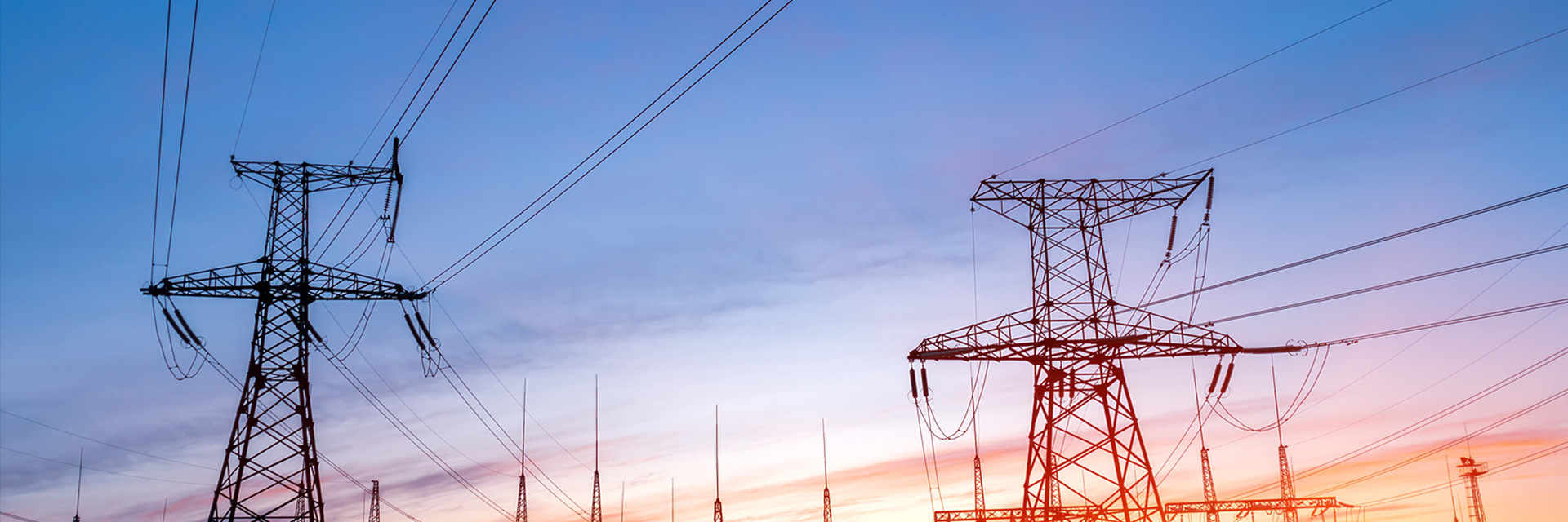


10kV power transformer
The winding adopts high-quality oxygen-free copper wire, which has good conductivity and low load loss. Winding design for the advanced longitudinal oil channel structure, good heat dissipation effect, high electrical insulation strength, good impact resistance.
Safe and reliable
Well-made
After-sales worry-free
Quality Assurance
Classification:
6kV-15kV oil-immersed transformer
Telephone:86-371-63719330
Product Introduction
10kV oil-immersed power transformer adopts new materials, new technology, new structure, optimized design and meticulous manufacturing.
The core material adopts high-quality silicon steel sheet with low magnetic conductivity and low loss. The structure is a rigid frame structure with good stability, low noise and strong short-circuit resistance.
The winding adopts high-quality oxygen-free copper wire, which has good conductivity and low load loss. Winding design for the advanced longitudinal oil channel structure, good heat dissipation effect, high electrical insulation strength, good impact resistance.
The body is pressed by high-strength electrical laminate, all leads are firmly clamped, and the structure is scientific and reasonable.
Plateau reinforced casing, suitable for high altitude areas.
This series of transformers set up a full range of protection devices, advanced technical performance, energy saving and environmental protection, safe and reliable.
Main implementation standards
GB1094、GB/T6451、JB/T3837、GB20052
Use of environmental conditions
1. Altitude ≤ 2500m
2. Maximum ambient temperature: 40 ℃
3. Maximum annual average temperature: 20 ℃
4. Maximum daily average temperature: 30 ℃
5. Minimum outdoor temperature: 30 ℃
Main technical parameters of S11-M-30 ~ 3150/10 oil-immersed distribution transformer
|
Model |
H-V |
Voltage combination and tap range |
L-V |
Bonding group |
No-load loss |
Load loss |
No-load current |
Sound power level |
short circuit impedance |
Total quality |
Long |
Overall dimension (mm) Wide |
High |
|
S11-M-30/10 |
6 6.3 10.5 11 |
± 2 × 2.5 |
0.4 |
Dyn11 |
0.10 |
0.63/0.6 |
2.0 |
50 |
4.0 |
280 |
730 |
450 |
995 |
|
S11-M-50/10 |
0.13 |
0.91/0.87 |
1.8 |
350 |
870 |
610 |
1005 |
||||||
|
S11-M-63/10 |
0.15 |
1.09/1.04 |
1.7 |
445 |
910 |
570 |
1080 |
||||||
|
S11-M-80/10 |
0.18 |
1.31/1.25 |
7.7 |
52 |
480 |
920 |
635 |
045 |
|||||
|
S11-M-100/10 |
0.20 |
1.58/1.50 |
1.6 |
550 |
825 |
665 |
150 |
||||||
|
S11-M-125/10 |
0.24 |
1.89/1.80 |
1.5 |
54 |
650 |
960 |
670 |
1180 |
|||||
|
S11-M-160/10 |
0.28 |
2.31/2.20 |
1.4 |
815 |
1010 |
730 |
1200 |
||||||
|
S11-M-200/10 |
0.34 |
2.73/2.60 |
1.3 |
56 |
970 |
1045 |
755 |
1240 |
|||||
|
S11-M-250/10 |
0.40 |
3.20/3.05 |
1.2 |
070 |
1080 |
800 |
1290 |
||||||
|
S11-M-315/10 |
0.48 |
3.83/3.65 |
1.1 |
58 |
1320 |
1120 |
840 |
1360 |
|||||
|
S11-M-400/10 |
0.57 |
4.52/4.30 |
1.0 |
1625 |
1170 |
900 |
1380 |
||||||
|
S11-M-500/10 |
0.68 |
5.14/5.15 |
1.0 |
60 |
1720 |
1195 |
960 |
1400 |
|||||
|
S11-M-630/10 |
0.81 |
6.20 |
0.9 |
4.5 |
2310 |
1470 |
1100 |
1600 |
|||||
|
S11- M300/1C |
0.98 |
7.50 |
0.8 |
62 |
2630 |
540 |
945 |
700 |
|||||
|
S11-M-1000/10 |
1.15 |
10.30 |
0.7 |
3030 |
1515 |
1150 |
1720 |
||||||
|
S11-M-1250/10 |
1.36 |
12.00 |
0.6 |
65 |
3405 |
2040 |
1220 |
1755 |
|||||
|
S11-M-1600/10 |
1.64 |
14.50 |
0.6 |
4110 |
2050 |
250 |
1944 |
||||||
|
S11-2000/10 |
2.05 |
20.90 |
0.5 |
5.0 |
4960 |
2180 |
2040 |
2340 |
|||||
|
S11-2500/10 |
2.50 |
25.00 |
0.4 |
67 |
5950 |
2335 |
2010 |
2435 |
|||||
|
S11-3150/10 |
3.10 |
33.00 |
0.4 |
70 |
7805 |
2510 |
2100 |
2510 |
Main technical parameters of S13-M-30 ~ 3150/10 oil-immersed distribution transformer
|
Model |
Voltage combination and tap range |
Bonding Group Label |
No-load loss |
Load loss |
No-load current |
sound power |
short circuit impedance Short- circut |
Total quality |
Overall dimension (mm) Out-LineDimentaion |
||||
|
Long mm |
Wide mm |
High |
|||||||||||
|
S13-M-30/10 |
6 10 |
±2x2.5 |
0.4 |
Dyn11 YynO |
0.08 |
0.63/0.60 |
1.6 |
50 |
4.0 |
290 |
810 |
450 |
1010 |
|
S13-M-50/10 |
0.10 |
0.91/0.87 |
1.6 |
395 |
885 |
615 |
1055 |
||||||
|
S13-M-63/10 |
0.11 |
1.09/1.04 |
1.5 |
560 |
940 |
680 |
1125 |
||||||
|
S13-M-80/10 |
0.13 |
1.31/1.25 |
1.5 |
52 |
565 |
930 |
635 |
1140 |
|||||
|
S13-M-100/10 |
0.15 |
1.58/1.50 |
1.4 |
630 |
790 |
715 |
155 |
||||||
|
S13-M-125/10 |
0.17 |
1.89/1.80 |
1.3 |
54 |
775 |
900 |
680 |
1235 |
|||||
|
S13-M-160/10 |
0.20 |
2.31/2.20 |
1.3 |
910 |
945 |
830 |
1255 |
||||||
|
S13-M-200/10 |
0.24 |
2.73/2.60 |
1.2 |
56 |
1055 |
960 |
820 |
1275 |
|||||
|
S13-M-250/10 |
0.29 |
3.20/3.05 |
1.1 |
1180 |
990 |
830 |
330 |
||||||
|
S13-M-315/10 |
0.34 |
3.83/3.65 |
1.1 |
58 |
1415 |
1035 |
925 |
1395 |
|||||
|
S13-M-400/10 |
0.41 |
4.52/4.30 |
1.0 |
1635 |
1485 |
1015 |
1385 |
||||||
|
S13-M-500/10 |
0.48 |
5.41/5.15 |
0.9 |
60 |
2155 |
1160 |
975 |
1605 |
|||||
|
S13-M-630/10 |
0.57 |
6.20 |
0.8 |
4.5 |
2385 |
1650 |
1185 |
1455 |
|||||
|
S13-M-800/10 |
0.70 |
7.50 |
0.8 |
62 |
3290 |
1560 |
920 |
1900 |
|||||
|
S13-M-1000/10 |
0.83 |
10.30 |
0.8 |
3540 |
1040 |
1075 |
2045 |
||||||
|
S13-M-1250/10 |
0.97 |
12.00 |
0.7 |
65 |
3950 |
1690 |
1015 |
2015 |
|||||
|
S13-M-1600/10 |
1.17 |
14.50 |
0.6 |
4840 |
1805 |
1250 |
2180 |
||||||
|
S13-2000/10 |
1.82 |
20.90 |
0.4 |
5.0 |
5950 |
2310 |
2140 |
2460 |
|||||
|
S132500/10 |
2.40 |
25.00 |
0.4 |
67 |
7275 |
2480 |
2200 |
2570 |
|||||
|
S13-3150/10 |
2.48 |
33.00 |
0.4 |
70 |
9360 |
2670 |
2340 |
2700 |
|||||
Note: The above are the national standard performance parameters. According to user needs, our company can provide products with different performance parameters.
For transformers of 500kVA and below, the load loss value on the slash in the table is applicable to D: connection group. The load loss below the slash applies to the 0 bonding group.
Our company produces on-load voltage regulation products according to user needs.
The total mass and external dimensions of the transformer are for reference only, and the actual dimensions are subject to the external drawings of the transformer.
Key words:
10kV power transformer
Related Products
Related Products
Product Consulting


